What is a Resistor? Series and Parallel combination of Resistors

The resistor is one of the most widely and commonly used electronic components. It plays a vital role in many electronic circuits. Generally, the resistor is made up of metal wire, designed to maintain a stable resistance in spite of any change in environmental conditions.
When supply is given to the resistor, it does not emit light but emits heat which is dissipated outside. When the current flows through the resistor, the heat is produced due to the electrical resistance present in it.
So what is resistance?
Resistance is the property of a resistor, by which it opposes the flow of electric current through it.
The resistance is denoted by the symbol R and its unit is Ohms(Ω).
By Ohm’s Law, the relation between current and voltage is given by V = R.I
Since the resistor dissipates the absorbed energy as heat, the power absorbed is given by
P = V . I = (I R) . I = I2 R Watts= V2/ R Watts
The resistance of any material is directly proportional to the length of the material and inversely proportional to the area of the cross-section of that material.
![]()
![]()
where ρ is the constant of proportionality, which is known as resistivity or specific resistance.
l is the length of the material and A is the area of cross-section of the material.
In a circuit, these resistors can be connected either in series or in a parallel fashion. There are also circuits that have a combination of both series and parallel resistors. Now, let us discuss, how the circuit behaves when the resistor is connected in series and in parallel.
Resistor in series
The resistor can be connected one after another to get a series combination of resistors. It is also called as cascade connection.
Consider the following circuit, in which three resistors R1, R2 and R3 are connected in series across the voltage source V. I is the current flowing from the source to all the elements.
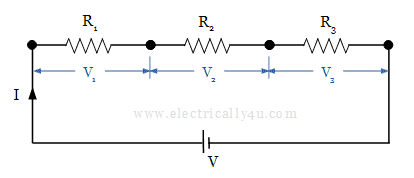
Since there is only one path for the flow of current, the same amount of current will flow through all the resistors. But the voltage gets dropped in three resistors R1, R2, R3 as V1, V2, V3 respectively. So we can write,
V = V1 + V2 + V3 ——- (1)
By Ohm’s law, We know V = I.R. Thus we can write,
![]()
![]()
Where Req = R1 + R2 + R3
This represents that the equivalent resistance of the series circuit is equal to the sum of all the individual resistance connected in series. For n number of series resistors, the equivalent resistance is
![]()
Resistors in Parallel
The resistors can be connected in parallel by connecting the one end of all the resistor terminals to one node and the other end of all the resistors are connected to another node.
The following circuit is considered, in which resistors R1, R2 and R3 are connected in parallel across the voltage source. I is the current flowing in the circuit from the supply.
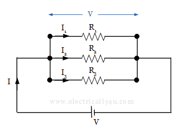
In this parallel combination of resistors, the current I gets divided into three parts I1, I2, I3 from node 1. The currents I1, I2, I3 flow through the resistors R1, R2, R3 respectively.
I = I1 + I2 + I3 ——- (2)
Since the voltage across two points will always be same, the voltage drop across the resistors R1, R2, R3 is equal to V.
By Ohm’s Law, the current through the resistors R1, R2, R3 is given by,
![]()
![]()
By Ohm’s law, we know that,
![]()
Thus by comparing the above two equations, we get,
![]()
If there are n resistors connected in parallel, then the equivalent resistance is given by,
![]()
When two resistors are connected in parallel, the equivalent resistance can be derived as,
![]()
![]()
Solved Problem
Let us do a problem to find the equivalent resistance in an electrical circuit that has both series and parallel resistors.
Determine the equivalent resistance between the terminals A and B in the below given circuit.
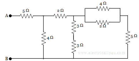
In the given circuit, there are various resistors between terminals A and B. To find the equivalent resistance, the circuit should be reduced from the opposite end of terminals A and B.
In the circuit, the resistors 4 Ω and 2 Ω are in parallel, as shown below.
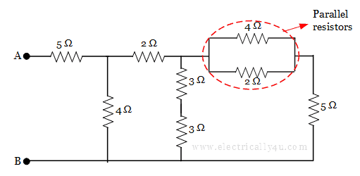
The equivalent resistance of the parallel resistor is
![]()
The circuit now becomes,
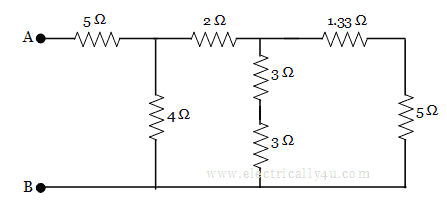
Now, 1.33 Ω and 5 Ω are in series, which will become 1.33 + 5 = 6.33 Ω.
Similarly 3 Ω and 3 Ω are in series, which will become 3 + 3 = 6 Ω. The circuit now becomes
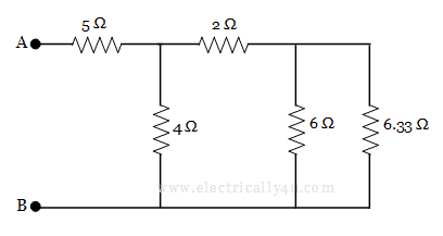
Now, it is observed that 6 Ω and 6.33 Ω are in parallel, the equivalent resistance for which is found to be
![]()
The equivalent circuit is redrawn as
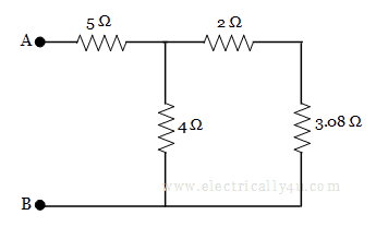
Now, it is found that 2 Ω and 3.08 Ω are in series, so 2 + 3.08 = 5.08 Ω. The equivalent circuit is then again redrawn as,
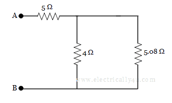
The resistors 4 Ω and 5.08 Ω are in parallel, the equivalent resistance is given by,
![]()
The circuit becomes,
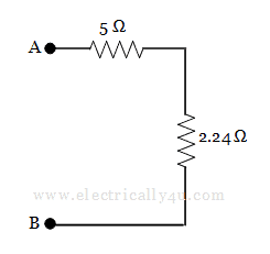
Finally, the two resistors 5 Ω and 2.24 Ω are in series, thus the equivalent resistance between the terminals A and B is
RAB = 5 + 2.24 = 7.24 Ω


Related Posts