Equivalent circuit and Phasor diagram of synchronous motor
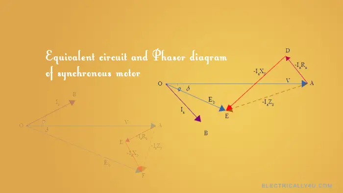
The phasor diagram of synchronous motor is used for understanding the behavior of the motor under different load conditions. We will discuss the easiest way of drawing the phasor diagrams of synchronous motor.
Before looking at the phasor diagram, we will have a look at the equivalent circuit of the synchronous motor.
Equivalent circuit of synchronous motor
Generally, a synchronous motor is a doubly excited system, which means two different excitations are given to the motor to rotate. A three-phase AC supply is given to the stator winding, which produces a rotating magnetic field.
Similarly, DC supply is given to the rotor winding. When this rotor rotates at synchronous speed, back emf is induced in the armature windings.
With that in mind, the equivalent circuit is drawn for the synchronous motor. The figure shown below shows the circuit model for one phase of a cylindrical type synchronous motor.
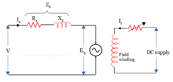
In the equivalent circuit,
V = Voltage applied to the armature per phase
Ia = armature current per phase
Ra = armature winding resistance in ohm per phase
XS = synchronous reactance per phase
Eb = induced back-emf per phase
If = exciting or field current
ZS = synchronous impedance per phase
It is given by Zs = Ra + jXs —–> (1)
When you apply Kirchoff’s voltage Law to the AC circuit loop in the equivalent circuit,
V = Eb + IaZs
V = Eb + Ia (Ra + jXs)
V = Eb + Ia Ra + jIa Xs —–> (2)
Eb = V – Ia Ra – jIa Xs —–> (3)
where IaRa is the voltage drop per phase in the armature resistance and IaXS is the reactive voltage drop per phase due to armature reactance and armature reaction effect.
Phasor diagram of synchronous motor
A 3-phase cylindrical rotor synchronous motor may operate at different power factors i.e., lagging, unity or leading. Accordingly, its phasor diagram is drawn with the help of the above equations. Before going into the section, learn how the synchronous motor behaves at no-load and load conditions.
Phasor Diagram for Lagging Power Factor
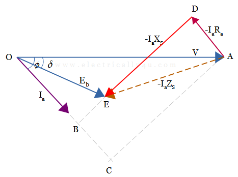
Let us consider the synchronous motor is drawing a lagging current from the supply. The phasor diagram is drawn by considering the equation(3). So to draw the phasor diagram, the phasor value of supply voltage is taken as reference, such that OA = V.
The armature current lags behind the input voltage, hence draw the phasor of armature current Ia lagging behind the voltage phasor V by the phase angle φ.
Draw the phasor of the voltage drop due to armature resistance from point A, in such a way that it is drawn opposite to the current phasor(AD = -IaRa).
From the extremity of this phasor(from point D), the voltage drop due to synchronous reactance is drawn perpendicular to the IaRa phasor(DE = -IaXS). Join AE, which gives the total voltage drop due to total impedance(-IaZS). Thus, Eb = V – Ia Ra – jIa Xs = V – Ia Zs
Join OE, which represents the phasor Eb, induced emf per phase. The phase difference between V and Eb i.e., angle δ is known as power angle or torque angle.
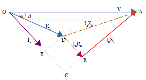
We can also draw the phasor diagram considering the other equation, V = Eb + Ia Ra + jIa Xs
Phasor Diagram for Unity Power Factor
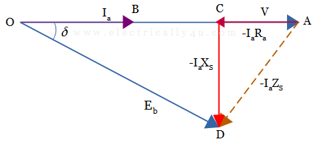
Let us consider the synchronous motor is drawing the current from the supply at the unity power factor. By considering equation(3), the phasor diagram is drawn.
Draw the terminal voltage as the reference phasor, such that OA = V. For unity power factor, the armature current is in phase with the voltage. Thus Ia is drawn on the voltage phasor itself, such that OB = Ia.
Draw the voltage drop phasor due to armature resistance from the extremity of the voltage phasor(from point A). It is drawn opposite to the current phasor, such that AB = -IaRa.
The drop due to synchronous reactance is drawn from point B. It is drawn in a direction perpendicular to the IaRa phasor, such that, BC = -IaXS. Join AC, which gives the total voltage drop.
Join OC, which represents the phasor Eb, back emf per phase. The phase difference between V and Eb is the torque angle δ.
Thus, Eb = V – Ia Ra – jIa Xs = V – Ia Zs
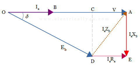
If you draw the phasor diagram by considering equation(2), it would look like the one below.
Phasor Diagram for Leading Power Factor
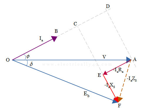
Now consider the synchronous motor is drawing a current from the supply at the leading power factor. Again, the same equation(3) is considered to draw the phasor diagram.
Draw the phasor value of supply voltage as a reference, such that OA = V.
The armature current leads the stator voltage, hence draw the phasor of armature current Ia leading the voltage phasor V by an angle φ.
Draw the phasor of the IaRa drop from point A, in such a way that it is drawn opposite to the current phasor(AE = -IaRa).
From the extremity of this phasor(from the point E), the IaXS drop is drawn perpendicular to the IaRa phasor(EF = -IaXS). Join AF, which gives the total voltage drop (-IaZS).
Join OF, which represents the phasor of induced emf per phase. Now, the phasor difference between V and Eb gives the load angle.
Hence, Eb = V – Ia Ra – jIa Xs = V – Ia Zs
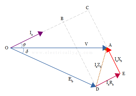
For the leading power factor, you can draw the phasor diagram by considering equation(2) as below.


Related Posts