Operation of Transformer on No load condition

A transformer is said to be at no load when the primary of a transformer is connected to the source of ac supply and the secondary is kept open. Similarly, a transformer at load condition indicates that the secondary is connected to the load.
In the previous article, we discussed the ideal transformer, which doesn’t have a core loss or copper loss. But in actual transformers, there will be a considerable amount of losses associated with the windings and core when it is operating at load conditions.
Before analyzing the transformer at load condition, it is important to understand the operation of the transformer on no load condition.
Operation and Phasor diagram
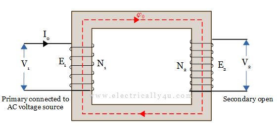
Consider the following practical transformer, where the primary winding is connected to the alternating voltage source and the secondary winding is kept open. It means the transformer is operated on no load condition.

When the transformer is connected on no-load, a small amount of current flows through the primary winding which is not purely reactive. This primary current under no-load conditions has to supply two losses.
- iron loss in the core, which includes both hysteresis loss and eddy current loss
- a very small amount of copper loss in primary winding (no copper loss in secondary as it is open).
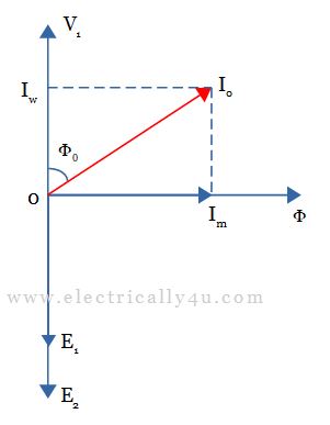
Hence, the no-load primary input current I0 does not lag behind the applied voltage V1 by 900 but lags behind V1 by an angle φ0 < 900.
No-load input power is given by
![]()
where cos φ0 is the power factor under no-load conditions. The phasor diagram of the transformer under no-load condition is shown in the following Figure.

As you can see in the above phasor diagram, the no-load current or the exciting current I0 has the following two components.
(i) First is the active or working or wattful or iron loss component. It supplies the iron loss plus a small quantity of copper loss in the primary winding.
![]()
(ii) The other component is the magnetizing or wattless component. Its function is to sustain the magnetic flux in the transformer core.
![]()
Thus the no-load primary current is obtained from the vector sum of the active component and magnetizing component.
![]()
Power factor lagging angle,
![]()
Points to Remember
The following points should be kept in mind while analyzing the transformer on no load.
- The no-load primary current Io is very small compared to the full-load primary current. Its value ranges from 2 to 5 percent of the full-load primary current.
- The no-load current I0 is made up of a relatively large magnetizing component Im, and a comparatively small iron loss component Iw, so the power factor of a transformer on no load is very small.
- Since the no-load primary copper loss is very small, it may be neglected. Thus the no-load primary input power is practically equal to the iron loss in the transformer (I0 = Iw).
- As core loss is the cause for the shift in the current phasor, the phase angle φ0 is also known as the hysteresis angle of advance.
- Since the permeability of the core material varies with the instantaneous value of the no-load primary current, the waveform of the magnetizing current is not truly sinusoidal. As such, it should not be represented by a phasor because only sinusoidally varying quantities are represented by rotating phasors. But, in practice, it makes no appreciable difference.
Solved Problem #1
A single-phase transformer of 3,300/220 V, 50 Hz takes a no-load current of 0.8 A and 500 W. Calculate (i) the active and magnetizing current (ii) its power factor.
Given: I0 = 0.8 A, V₁ = 3300 V, W0 = 500 W
Solution:
(i) The active component of no-load current is obtained from the no-load input power.
![]()
![]()
![]()
The magnetizing component is obtained from,
![]()
![]()
(ii) To obtain the power factor, let us use the no-load input power formula
![]()
![]()
![]()


Related Posts